Technologies
SeismicCity’s technology includes a series of unique proprietary prestack depth migration algorithms developed with the objective of constructing accurate and reliable depth migrated seismic data. These are combined with commercial software used for interpretation and model building. SeismicCity’s prestack depth migration algorithms are implemented using hybrid CPU / GPU computer clusters.
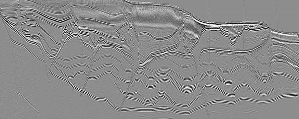
Prestack depth migration
Our series of prestack depth migration algorithms are built to answer imaging requirements of any geological setting. These include wave based Reverse Time Migration (i.e. “RTM”) algorithm, and ray based Kirchhoff summation algorithms using the wave front reconstruction method for calculation of travel times.
The input to our depth migration algorithms can be in any order. Both wave based and ray based algorithm include internal sorting mechanism. The prestack depth migration algorithm can handle any kind of anisotropic field.
Our prestack depth migrations are highly versatile and can handle both off-shore as well as on-shore data, recorded in narrow azimuth or wide azimuth manner.
SeismicCity RTM algorithm is based on proprietary recursive operators for application of spatial derivatives, enabling migration of high frequencies with minimal amount of numerical dispersion.
- Common shot / common receiver implementation
- Uses a non-smooth velocity model
- Capable of imaging turning waves as well as prism waves
- Based on proprietary recursive operator for application of spatial derivatives
- Includes isotropic as well as anisotropic imaging
- Is based on the wavefront reconstruction algorithm for calculation of traveltime functions
- Includes isotropic as well as anisotropic imaging
- Capable of imaging turning waves
- Produces multi-azimuth gathers to be used in multi-azimuth velocity estimation
- Preserves the relative amplitude of the data
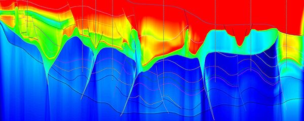
Velocity and Anisotropy Estimation
We are using two methods for velocity analysis and construction of the layered velocity fields. The first tool is reflection tomography. Reflection tomography is a grid or layer based global inversion technique. It is based on iterations of full volume prestack depth migration, where at each iteration residual curvature is analyzed on image gathers and is input to a minimization process. The tomographic inversion and update which we are using is built to optimize the velocity field, as well as anisotropic delta and epsilon fields. A fully TTI model can be optimized for use in TTI prestack depth migration when dip and azimuth fields are input.
The second velocity analysis and update tool which we offer is a prestack depth migration scan. In this method, a series of prestack depth migrations are executed, each with a different trial velocity or anisotropic parameters. The resulting image gathers or full sections are analyzed for selecting the optimal velocity and anisotropic field.
For generation of dip and azimuth volumes we use a unique tool that inputs the main geological surfaces and construct dip and azimuth volumes at the spacing needed for application of prestack depth migration. The dip and azimuth volumes together with delta and epsilon anisotropic volumes and the vertical velocity field are the five parameter volumes input to TTI prestack depth migration algorithms.
Interpretation and model building
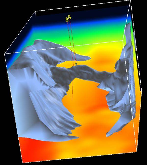
Construction of accurate velocity models is based on repeat iterations of trial models and adjustment of these models based on the trial image. This involves repeat interpretation of the depth migrated volumes. In most cases, the interpretation work requires tools that can handle complex geological settings such as multiple salt bodies or complex overthrust structures. Our interpretation and model representation is based on GoCad technology. The interpreted surfaces are input to GoCad as 3-dimensional curves linked together to form complex surfaces, and then combined to form closed shape geometrical volumes and geological units.
The interpretation work is completed with construction of geological units and then linked with the velocity analysis results supplying the velocity field and anisotropic field of each geological unit. The 3-dimensional models are stored as volumes which can be used by any of our prestack depth migration or simulation algorithms.
With our advanced interpretation tools we are able to assist our clients with the interpretation work required during the model building phase. The final GoCad model is delivered to our clients at the end of the depth imaging project in various formats that can be loaded to any commercial interpretation system.
For addressing model building and depth imaging projects that require the use of a faulted anisotropic model, SKUA technology is used for the construction of complex faulted models.
Simulation
3-dimensional wave equation.
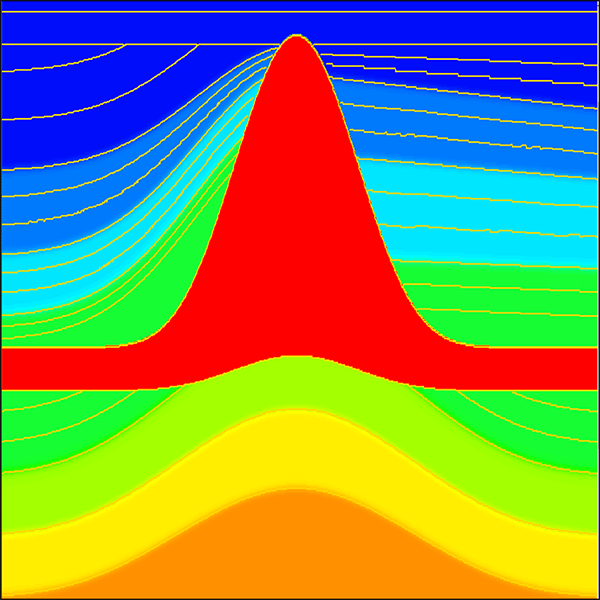
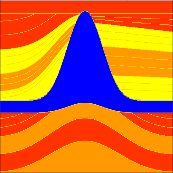
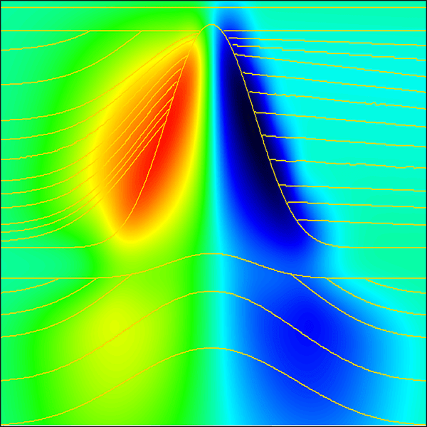
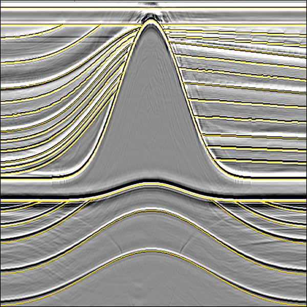
We are offering simulation tools based on a 3-dimensional solution of the full wave equation. This involves construction of a detailed 3-dimensional model, simulation and recording of common shot gathers, and then application of prestack depth migration imaging. Simulation is done using a recursive operators forward time modeling (“FTM”) algorithms and can be done for any anisotropic media. Based on the objective of the project, either absorbing surface or free surface can be used during simulation, enabling creation of surface related multiples.
The 3-dimensional simulation is used for (a) data analysis and (b) to assist in seismic acquisition design (See "The Tempest Project”). For data analysis a synthetic dataset is generated and then migrated. Comparing the synthetic preSDM volume to the field data preSDM volume we can differentiate real geological reflections from seismic noise patterns. This can be done only using wave equation simulation where the model is known. Illumination maps and volumes are generated as part of the data analysis.
The use of 3-dimensional simulation to assist in acquisition design has been growing in the past few years. Due to the complexity of new wide azimuth and OBN acquisition setup and parameters, new tools are needed to assist in the design work. Using wave equation simulation we can simulate various acquisition patterns, and as well record simulated data that will help in the selection of processing and imaging techniques. This can greatly help in both reducing the costs of the field data acquisition as well as obtaining higher quality field data.
Computer hardware
Prestack depth migration, wave equation simulation and velocity analysis algorithms all require a high-end computational configurations. A key part of our technology is a continual upgrade of our hardware technologies to the latest available. The constant change in prestack depth migration algorithms requires constant modification and optimization of our computer environment to support the increased demand in computational speed as well as data transfer and storage. The development of our computer environment is linked to the way our algorithms are implemented, resulting with an optimized hardware/software solution.
In the past several years, the industry has moved from imaging by solution of the one-way wave equation to imaging using a solution of the two-way wave equation (i.e. RTM). The hardware configuration which is needed for implementation of RTM is much larger than the one needed for implementation of one-way wave equation, or ray based imaging using rays or beams. In order to offer RTM solution to our clients in a timely manner, we needed to increase our computing power. We achieved this task by upgrading our computer design from CPU based hardware to the newest hybrid CPU / GPU implementation based architecture.


